Introduction
In industrial automation, RS485 remains the gold standard for long-distance, noise-resistant serial communication. However, connecting a Modbus RTU sensor (like temperature, humidity, or pressure probes) to a modern PC requires more than just a cable. It requires a stable USB-to-RS485 bridge and a robust software master like QModMaster to orchestrate the data exchange.
This tutorial covers the entire workflow—from physical wiring to advanced register polling—ensuring you can troubleshoot any Modbus slave device with confidence.
Required Hardware Checklist
| Component | Specifications | Purpose |
|---|---|---|
| RS485 Sensor | Modbus RTU Compliant | The Slave device providing data. |
| USB to RS485 Adapter | FTDI, CH340, or CP2102 | Bridge between Serial and PC USB. |
| Power Supply | 5V, 12V, or 24V DC | Most sensors require external power. |
| QModMaster | v0.5.2 or v0.5.3-beta | The Software Master simulator. |
Step 1: Physical Wiring (The RS485 Bus)
RS485 uses Differential Signaling via a twisted pair. Unlike RS232, which is point-to-point, RS485 allows multiple sensors on the same bus. Follow this standard wiring logic:
- Connect A+ on the sensor to A+ on the USB adapter.
- Connect B- on the sensor to B- on the USB adapter.
- Note: Some manufacturers swap A/B labels. If it fails, try reversing them.
- Most industrial sensors require 12V-24V DC.
- Connect the GND of the power supply to the GND of the sensor.
- Ensure a common ground between the sensor and the USB adapter if possible.
Step 2: Windows COM Port Verification
Before opening QModMaster, you must ensure your PC recognizes the USB-to-RS485 adapter. Without a valid Virtual COM Port (VCP) driver, the software cannot access the serial hardware.
- Plug in your USB-to-RS485 adapter.
- Right-click the Start button and select Device Manager.
- Expand the Ports (COM & LPT) section.
- Look for an entry like
USB-SERIAL CH340 (COM3)orSilicon Labs CP210x (COM5). - Pro Tip: If you see a yellow exclamation mark, you need to download the specific driver for your chipset (FTDI, CH340, or CP2102).
Step 3: Setting Up the Modbus RTU Connection
Now that your hardware is recognized by Windows, launch QModMaster. We need to tell the software exactly how to talk to your RS485 bus. Most sensors use a default configuration, but you must match these settings precisely.
1. Modbus Mode Selection
Go to the top menu and select Options > Modbus RTU. Unlike Modbus TCP which uses Ethernet, RTU (Remote Terminal Unit) is the specific protocol for serial RS485 communication.
2. Serial Port Parameters
Click on Options > Serial Port. A dialog box will appear. Fill in the following based on your sensor’s manual:
90% of industrial RS485 sensors (Temperature/Humidity/Soil) default to 9600 Baud, 8 Data Bits, No Parity, and 1 Stop Bit. If you are unsure, try this combination first.
Connecting to the Bus
Once the parameters are set, click the Connect icon (the plug symbol) or go to Commands > Connect.
Status Check: Look at the bottom status bar of QModMaster. It should say CONNECTED. If you see “Error opening serial port,” ensure no other software (like a PLC IDE or Serial Monitor) is currently using that COM port.
Step 4: Reading Sensor Data
Being “Connected” only means the serial port is open. To actually see your sensor’s temperature or humidity, you must send a specific Request Frame. This requires three pieces of information from your sensor’s Modbus Map (Data Sheet).
The unique address of your sensor on the RS485 bus.
Default: Usually 1.
Range: 1 to 247.
Tells the sensor what action to perform.
Read Registers: 03 (Read Holding) or 04 (Read Input).
Write: 06 (Single) or 16 (Multiple).
The specific “slot” where data is stored.
Example: Address 0000 might be Temp, 0001 might be Humidity.
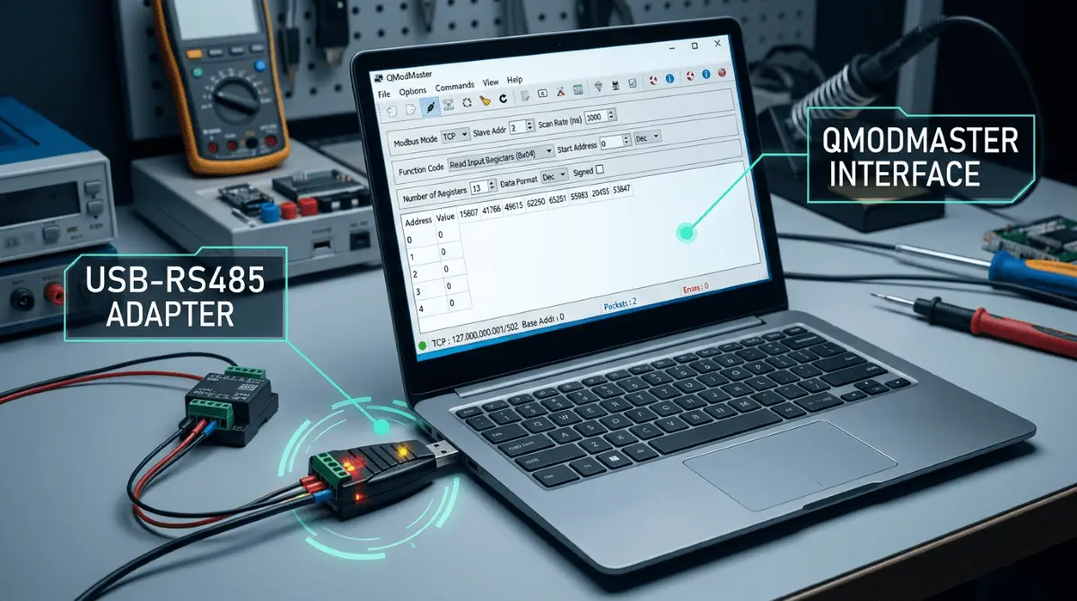
Applying Settings in QModMaster Interface:
- 🔹 Set Slave ID in the top-left box (labeled “Slave ID”).
- 🔹 Select Read Holding Registers (03) from the “Function Code” dropdown.
- 🔹 Enter the Start Address (e.g., 0) and Number of Registers (e.g., 2).
- 🔹 Click the Scan icon (the blue loop) or press F5 to start polling.
If your sensor manual says “Address 40001,” Modbus software usually expects 0 or 1. Commercial manuals often use “PLC Addressing” (40xxx), while QModMaster uses raw protocol addresses. Always try subtracting 1 if you get an “Illegal Data Address” error.
Step 5: Using the Bus Monitor for Debugging
If your register table remains empty or shows “0”, the Bus Monitor is your best friend. It shows the raw Hexadecimal traffic flowing between your PC and the sensor. To open it, go to View > Bus Monitor.
Common Error Codes & Fixes
If you don’t see the clean Tx/Rx exchange above, refer to this troubleshooting table:
| Symptom / Error | Root Cause | Solution |
|---|---|---|
| Timeout Error | No response from sensor. | Check wiring (A/B swap), power supply, or incorrect Slave ID. |
| CRC Error | Data is corrupted. | Check Baud Rate, Parity, or use a shielded cable for RS485 noise. |
| Illegal Function | Sensor doesn’t support code. | Try 04 (Input Reg) instead of 03 (Holding Reg). |
| Illegal Data Address | Register doesn’t exist. | Check your manual for the correct start address (try 0 or 1). |
Pro Tip: Floating Point Data
If you see strange large numbers instead of temperature values, your sensor might be using 32-bit Float. In QModMaster, go to View > Data Format and select Float or Swapped Float to correctly decode the two 16-bit registers into a single decimal value.
Conclusion: Mastery Over the Bus
Connecting an RS485 sensor using QModMaster is a fundamental skill for any automation engineer. By following this structured approach—verifying physical wiring, matching serial parameters, and analyzing raw Hex traffic—you can bridge the gap between hardware sensors and actionable data.
🛡️ Expert Tip: The Termination Resistor
If your connection works perfectly on your desk but fails in the field with long cables (over 10 meters), you likely need a 120-ohm termination resistor. Place the resistor between the A+ and B- lines at the very last sensor on the bus. This prevents signal reflection and is the #1 fix for “Ghost” CRC errors in industrial environments.
Ready to Start Debugging?
Ensure you are using the most stable version of QModMaster for your operating system.
Go to Download Center →Frequently Asked Questions
Expert solutions for common Modbus RTU and RS485 challenges.
Q: Why do I get a “Timeout” error even though my wiring is correct?
A: This is usually caused by a Slave ID mismatch or an incorrect Baud Rate. Most sensors default to ID 1 and 9600 bps. Also, ensure your USB-to-RS485 adapter is assigned to the correct COM port in QModMaster’s Serial Port settings. If using a long cable, check if the sensor requires a higher voltage (e.g., 24V instead of 12V) due to voltage drop.
Q: How many RS485 sensors can I connect to one QModMaster instance?
A: Technically, the Modbus RTU protocol supports up to 247 slave devices on a single bus. However, physical RS485 transceivers usually support 32, 64, or 128 nodes depending on the “Unit Load.” To poll multiple sensors, you must change the Slave ID in the QModMaster interface for each request.
Q: What is the difference between Function Code 03 and 04?
A: Function Code 03 is for “Read Holding Registers” (read/write memory), while Function Code 04 is for “Read Input Registers” (read-only data from the physical process). If you use the wrong code, the sensor will likely return an “Illegal Function” (Exception Code 01) error. Always check your sensor’s Modbus map.
Q: Can QModMaster handle 32-bit Integer or Floating-point values?
A: Yes. Since Modbus registers are 16-bit, a 32-bit value spans two consecutive registers. In QModMaster, you can use the Data Format menu to select Float, Swapped Float, or Long (Int32) to automatically combine and decode these registers into a human-readable number.